


Ch.1
A METHOD TO ALTER POLYMER SWELLING PERMANENT TOPOLOGICAL EFFECTS
Cat Bromels, Anna Railanmaa, Don Lupo, and Charles Tonkin
Introduction
Real-time health monitoring, Internet of Things devices (IoT), and sensors are in ever-increasing demand. Development of smaller, ultraflexible wearable devices are at the forefront of research to meet these demands (21). Printed and organic electronics offers proven and patented, low-cost, high processing volume products that are recyclable or incinerable with standard household waste (9, 12, 16, 17, 21). For these types of small temporary devices, cost and end of life disposal must be considered; for wearables, additional concerns of flexibility, minimal profile, unobtrusive devices that contain only non-toxic and non-corrosive materials must be considered during research if results are to be useful for production-level applications.
Though rigid batteries (printed or otherwise) can meet the energy requirements of wearable health-monitoring systems, they are typically too bulky to be worn comfortably, and printed flexible batteries available currently are cost prohibitive. Additionally, batteries generally contain noble or heavy metals—such as lithium, silver, or manganese—which are corrosive and difficult to dispose of (5, 9, 10). Autonomous printed energy harvesting systems (e.g. ambient light, radio-frequency fields, vibrations, etc.) can provide enough energy and printed supercapacitors can provide the backup storage needed to fuel systems when the primary energy source is not available (2, 5, 7, 12, 21). Additionally, both of these solutions can be printed with completely non-toxic, non-corrosive materials that are environmentally friendly, and that pose no adverse reactions to the end-user in the event of a mechanical breakage (5, 9, 10, 12, 16, 21). It should be noted that the only portion of a supercapacitor which has the potential to leak out of the device is the electrolyte, but studies have proven that non-corrosive and non-toxic aqueous alternatives, (e.g. table salt and water) are viable (10, 18).
Supercapacitors—also known as ultracapacitors or electric double-layer capacitors (EDLC)—are rechargeable electrochemical energy storage devices that can store and release energy almost instantaneously. Their basic construction is two porous electrodes connected to current collectors with a separator and electrolyte between them, all of which can be fabricated using non-toxic biodegradable or incinerable materials (5, 7, 9, 10, 11, 13, 16, 18, 20). Additionally, supercapacitors have a low production cost, are well studied, and are already in use for a variety of applications from standalone low-power electronics to grid-level electrical storage (5, 11).
Background
This study builds upon the printed supercapacitor research at the Laboratory for Future Electronics at Tampere University (formerly Tampere University of Technology). Flexible super- capacitors have been previously fabricated on paper or PET substrates (7, 8, 10, 12, 13, 16, 18) which are not ideally suited for skin-conformable, wearable applications. Thermoplastic Polyurethane (TPU) was chosen as an ideal substrate for development of skin-mountable devices. Covestro Platilon® 4201 AU 50μm was chosen for its high elasticity, use in current medical applications, documented printability, and breathable but watertight properties. The current collector ink— Henkel Electrodag® PF407C graphite ink—from previous studies (10, 13, 16) was chosen for its low resistivity (10 Ohm/square [Ω/□] as specified by manufacturer), incinerable properties, and its ability to be prepared in any environment.
A key performance parameter of a supercapacitor is the Equivalent Series Resistance (ESR), which limits the maximum discharge current. Although extremely rapid discharge is not a major issue for printed supercapacitors for use in distributed smart devices—in contrast to applications such as grids or electric vehicles—the ESR still needs to be low enough to power measurements and possible radio transmissions. For supercapacitors using metal-free current collectors, it was found that the largest contributor to ESR is the sheet resistance of the current collector (13). Additional factors contributing to the ESR include the resistivity of the electrode (including the resistivity of the electrolyte within its porous layer) and the contact resistance between the electrode and the current collector (14, 22). The current collector is responsible for charge transport during the charge-discharge process, and research has indicated that increasing interfacial contact between the current collector and the electroactive materials will increase efficiency, increase rate capability, decrease impedance, lower the charge transfer rate, and improve storage capability (14, 22).
Fabrication and Measurement Baseline
The capacitance of a printed supercapacitor is directly linked to the thickness and surface area of the electrode (13). For this reason, screen printing is often utilized as the production method, as this technique can produce thick, uniform layers in a single pass (13, 21). Laboratory-level fabrication bar-coating with stencils has been shown to provide similar results to production-level screen printing (13) and was used in this study. Current collector sheet resistance can be correlated with equivalent series resistance (ESR) of a supercapacitor (13). This study focused only on the optimization of the printing of the current collector, rather than on assembly of complete devices. Sheet resistances were measured with the 4-point probe method (19) on a Zahner Elektrik Zennium Electrochemical Workstation over the range of -200 – 200 mV, with a scan rate of 50mV/s.
TPU sheets were cut to approximately 270mm square and wrapped—with minimal stretching of the substrate—around a 250mm square, 2.5mm-thick sheet of aluminum via 3M 810 scotch tape on the edges. This was done to ensure that the TPU stayed taut during printing, transport, and heat setting in a convection oven. A 20mm x 30mm stencil made of 120μm stainless steel was used to blade coat the graphite ink. The initial oven setting was 15 minutes at 120°C; one pass of ink was applied per current collector, as per previous settings for PET substrates (10, 13).
Initial Results
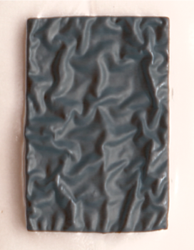
The first thirty-one test sample variants printed were unusable due to extensive topological malformation (Fig. 1). It was determined that this malformation was the result of polymer swelling caused by the 2-(2-Butoxyethoxy) ethanol 112-34-5 in the ink. Swelling occurs when a solvent enters a solid but does not dissolve it; in the case of polymers with multiple chain types, swelling may occur unevenly across the chains, creating high levels of stress at areas of cross-linking.
Thirty-one unsuccessful attempts were made to reduce the impact of the polymer swelling via substrate surface treatments or coatings, substrate heat pre-treatments, and oven heat and/or timing changes. It was found that if the ink was allowed to dwell at room temperature on the substrate prior to oven heat setting, the polymer swelling topological changes would begin to reverse. Even at a dwell time of 10 minutes, the permanent malformation after heat setting was too great for the current collectors to be used, and since dwell times of that length would be inappropriate for production-level fabrication, no additional study on dwell times was conducted. Sheet resistance measurements were taken from the nineteen (all others being too malformed for readings to be performed), with an average sheet resistance of 22 Ω/□ ±10 Ω/□. None of these samples passed the tape test with the majority of the ink film being removed.
Results
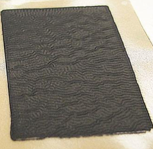
It was determined that the best method to retain the natural surface topology of the TPU was to stabilize it while printing and heat curing, in order to force the polymer chains to remain flat along the z-axis while swelling was occurring. Because the intended end-use supercapacitor electrolyte is water-based, it was known that some form of barrier would be needed to encapsulate the supercapacitors to eliminate or reduce evaporation (8, 16). Additionally, for a wearable, skin-conformable device, one side of the supercapacitor would be required to have an adhesive layer.
The stabilization method used 3M 468MP Adhesive Transfer Tape, as it is flexible and has heat resistance up to 204°C, and was successful. Samples were made by applying a 40mm x 40mm adhesive patch on the backside of the TPU in areas to be printed. This left 5mm excess tape on all sides of the printed area if perfectly centered, which was enough space to perform printing alignment by visually aligning the print when using a stencil. The TPU was secured to the aluminum sheet in the same method described above and several heat setting temperatures and times were examined, with 15 minutes at 130°C providing the lowest sheet resistance (12 Ω/□ ±7 Ω/□). Additional tests were made by adding ink passes before heat setting (two and three passes), which lowered the resistance to 7 Ω/□ ±2 Ω/□, and adding one ink pass after heat setting and then either re-heat setting with the same parameters, which raised the sheet resistance slightly (8 Ω/□ ±2 Ω/□), and at 25 minutes at 130°C which greatly lowered the resistance variability between samples (7.5 Ω/□ ±0.4 Ω/□). Samples made using these methods passed the tape test with minimal—if any—ink film being removed.
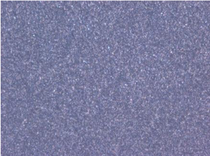
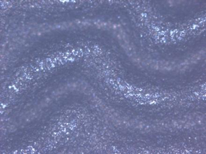
In the 3M adhesive stabilized TPU samples, there is a wave pattern that appears (Fig. 2c). By comparing samples printed on PET vs. those with the wave pattern under magnification, it can be seen that the ink film thickness is uneven (IFT) (Fig. 2a and 2b). Due to lack of access to a scanning electron microscope (SEM), it is difficult to measure the variations in IFT of the wave pattern. A possible reason for the decreased sheet resistance may be that this pattern plays some role in increasing the surface area of the current collector, allowing for a faster movement of charge carriers; this type of resistance decrease has been noted in research done on nanostructured current collectors (14, 15).
Conclusion
When working with TPUs in conjunction with inks containing solvents, polymer swelling can be unpredictable and difficult to address phenomenon. However, it can also be manipulated to beneficial effect. Additional study needs to be conducted to determine if adhesive stabilization as described here is effective with other TPUs or copolymers that exhibit permanent swelling malformation, as well as determining (via SEM for example) if the wave pattern as seen is indeed creating a larger surface area, to what degree, and if there is a correlation with sheet resistance values.
A removable stabilization adhesive (3M SCPS-100 Prespacing Tape) was tested at the end of the research period4. There was no surface malformation of the TPU and acceptable sheet resistances (10 Ω/□ ±2 Ω/□) both before and after the stabilization layer was removed. However, due to the very small number of samples that were tested, the results were not deemed conclusive.
Drying tests were also conducted to determine how effectively the 3M tape acted as a barrier to prevent evaporation of the aqueous electrolyte. However, though it was determined that evaporation at room temperature was less than 0.002 grams over seven days with the 3M adhesive stabilization layer, tests without this layer were inconclusive, so a comparison could not be made. Without fabricating an entire supercapacitor and conducting characterization tests, conclusions as to whether the evaporation rate is acceptable would be speculative.
Acknowledments
ThinFilm Scholarship
PAUL-Project
Laboratory of Future Electronics at Tampere University | TAU
References
- Abbott, S. Solubility Science: Principles and Practice. (Self).
- Bae, J. et al. Fiber Supercapacitors Made of Nanowire-Fiber Hybrid Structures for Wearable/Flexible Energy Storage. Angewandte Chemie International Edition 50, 1683–1687 (2011).
- Bittrich, E. et al.Polymer Surface Characterization. (De Gruyter, 2015).
- Brønsted, J. N. & Volqvartz, K. Solubility and swelling of high polymers in ternary mixtures. Trans. Faraday Soc.35,619–624 (1940).
- Dyatkin, B. et al. Back Cover: Development of a Green Supercapacitor Composed Entirely of Environmentally Friendly Materials (ChemSusChem 12/2013). ChemSusChem 6, 2396–2396 (2013).
- Han, C. D. Rheology and processing of polymeric materials. (Oxford University Press, 2007).
- Keskinen, J. et al. Lifetime and reliability of flexible aqueous supercapacitors: constant voltage floating and bending experiments. 2018 7th Electronic System-Integration Technology Conference (ESTC) (2018). doi:10.1109/estc.2018.8546412
- Keskinen, J. et al. Printed supercapacitors on paperboard substrate. Electrochimica Acta 85, 302–306 (2012).
- Keskinen J., Railanmaa, A. & Lupo, D. Monolithically prepared aqueous supercapacitors. Journal of Energy Storage 16, 243–249 (2018).
- Keskinen, J. et al. Architectural modifications for flexible supercapacitor performance optimization. Electronic Materials Letters 12, 795–803 (2016).
- Lehtimäki, S. et al. Low-cost, solution processable carbon nanotube supercapacitors and their characterization. Applied Physics A 117, 1329–1334 (2014).
- Lehtimäki, S. et al. Performance of printable supercapacitors in an RF energy harvesting circuit. International Journal of Electrical Power & Energy Systems 58, 42–46 (2014).
- Lehtimäki, S. et al. Performance, stability and operation voltage optimization of screen-printed aqueous supercapacitors. Scientific Reports 7, (2017).
- Liu, L. et al. Evaluatinag the Role of Nanostructured Current Collectors in Energy Storage Capability of Supercapacitor Electrodes with Thick Electroactive Materials Layers. Advanced Functional Materials 28, 1705107 (2017).
- Liu, L., Zhao, H. & Lei, Y. Review on Nanoarchitectured Current Collectors for Pseudocapacitors. Small Methods 1800341 (2018). doi:10.1002/smtd.201800341
- Pettersson, F. et al. Printed environmentally friendly supercapacitors with ionic liquid electrolytes on paper. Journal of Power Sources 271, 298–304 (2014).
- (C16) Porhonen, J., Rajala, S., Lehtimaki, S. & Tuukkanen, S. Flexible Piezoelectric Energy Harvesting Circuit With Printable Supercapacitor and Diodes. IEEE Transactions on Electron Devices 61, 3303–3308 (2014).
- Railanmaa, A., Lehtimäki, S. & Lupo, D. Comparison of starch and gelatin hydrogels for non-toxic supercapacitor electrolytes. Applied Physics A 123, (2017).
- Smits, F. M. Measurement of Sheet Resistivities with the Four-Point Probe. Bell System Technical Journal37,711–718 (1958).
- Zhang, H., Qiao, Y. & Lu, Z. Fully Printed Ultraflexible Supercapacitor Supported by a Single-Textile Substrate. ACS Applied Materials & Interfaces 8, 32317–32323 (2016).
- Zhao, H., Liu, L., Fang, Y., Vellacheri, R. & Lei, Y. Nickel nanopore arrays as promising current collectors for constructing solid-state supercapacitors with ultrahigh rate performance. Frontiers of Chemical Science and Engineering 12, 339–345 (2018).


